Benefits of Using Split Core Transformers

Amorphous Core, Nanocrystalline core, current transformer core, EMI core, EMC core, Common mode choke core, Common mode core, Amorphous C core, Amorphous Transformer Core, Split Core

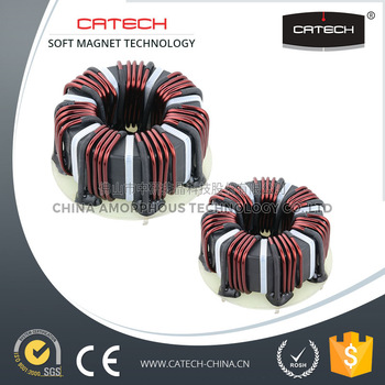
If you’re looking at current transformers core , you truly have two options: split core transformer and strong center transformer. A contactless, split core transformer’s principle specialty is its capacity to be snapped over previous wires, making them perfect for retrofitting undertakings and that’s just the beginning. There is no compelling reason to screw or weld any kind of bracketry, so they are anything but difficult to introduce. Likewise, they can be introduced inside an electrical control boards, which enable you to stay away from complex and periodically costly wiring. They can be introduced in a live framework without the stress of meddling with its present operation, settling on it the perfect decision for engineers hoping to plan a power meter system.

Split core transformers are intended to screen an assortment of remotely found gadgets that might be situated in ranges that are out of reach or work under cruel conditions. Remotely screen gadgets that occasionally work in blocked off or unforgiving conditions.

Lamentably, the advantages that go with split core transformers are additionally joined by a less helpful component: cost. Specialists likewise view them as fairly less precise than a strong center transformer. This is the reason it is critical to comprehend the contrasts between a split center and strong center transformer before settling on the decision as to which gadget to utilize.

SPLIT CORE
Split core CURRENT transformer

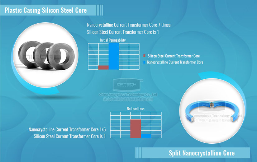
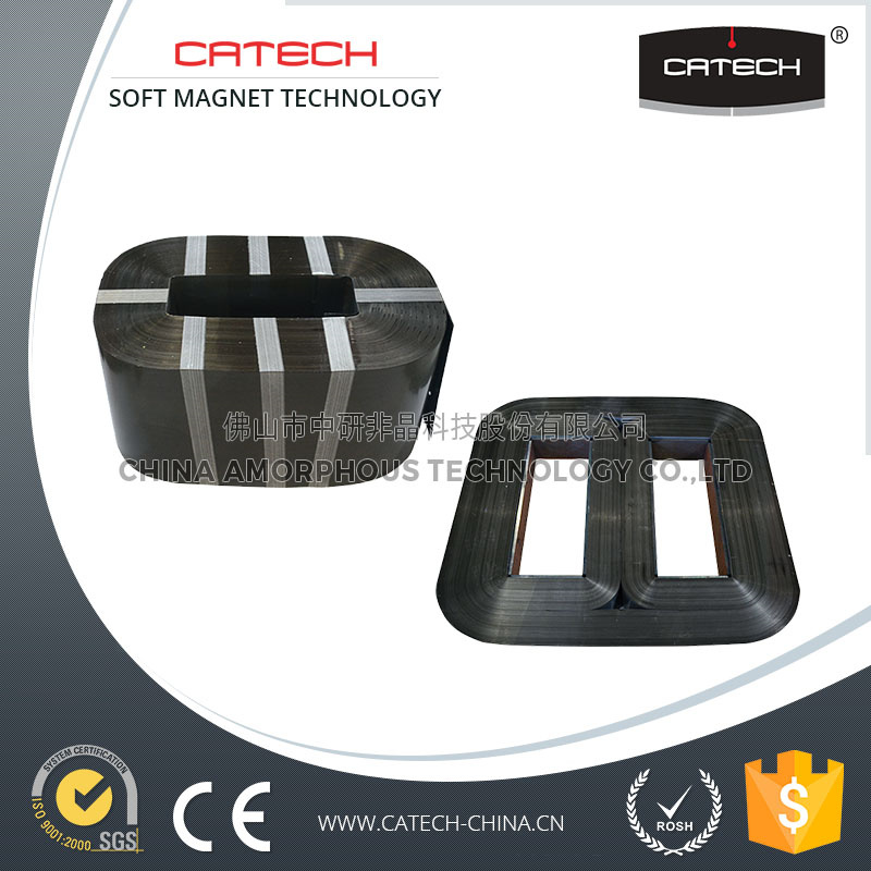
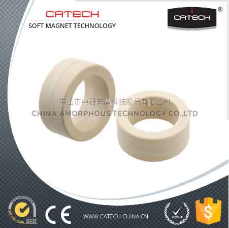
Split core current transformers are made similarly as a strong center transformer with one noteworthy contrast. The core is made in two particular pieces that are effectively isolated. Since the center is isolated into two separate pieces, split center transformers are liable to mistakes because of the two pieces not reaching consistently. What’s more, the auxiliary windings are not as consistently dispersed around the center as they are in strong center transformers. In light of this inadequacy, split core transformers are not the ideal decision for all applications.

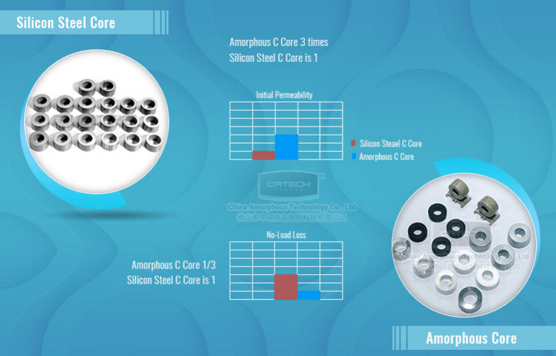
There are a few unique sorts of split core transformers that can be utilized as a part of various applications. For instance, the FeSi split core transformer is one of the more moderate alternatives. In any case, it produces poor linearity, particularly at bring down streams, improving it suited for measuring high ebbs and flows just where precision isn’t as imperative as getting an unpleasant estimation of energy utilization. These transformers are likewise cumbersome and substantial, implying that it has particular physical restrictions for utilize.

On the off chance that you are searching for something more exact, a FeNi split center transformer makes a decent showing with regards to. These offer better measuring execution, even under little current conditions. Be that as it may, they are likewise more costly. FeNi split core transformers additionally battle with linearity and consume up more room in your board and office.

Ferrite split core current transformers are another choice for those searching for a split center transformer arrangement. Ferrite transformers have made some amazing progress in the course of recent years so as to make a superior, more exact observing arrangement. The more up to date ferrite transformers have enhanced penetrability and can be utilized as a part of an extensive variety of energy checking applications, supplanting both FeSi and FeNi transformers, even with a low attractive immersion level. They give a financially savvy other option to FeSi and FeNi transformers.

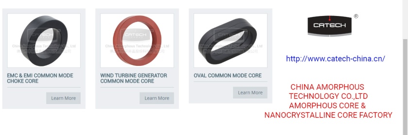
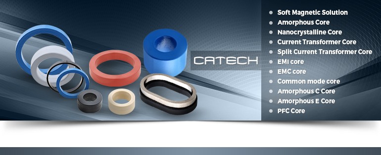
Are you searching for a quality and best current transformers core manufacturing company. please visit CATECH.

CATECH is the wholesale and retail global supplier of split core in China

Go here for a full review of Split Core China

See Related Stories

Also Read:

Current Transformer Core China

Amorphous Core, Nanocrystalline core, current transformer core, EMI core, EMC core, Common mode choke core, Common mode core, Amorphous C core, Amorphous Transformer Core, Split Core

Versatility and finding the right plan together with our customers is the key point in this area. EPRO can make a stunning arrangement of decisions. All best in class focus materials can be used for accomplishing exactness classes up to 0,2S, single focus or multi focus ring focus current transformers or outstanding customer wishes as specific shading codes on connectors, compensation of appealing field and various more choices are available.

All around EPRO offers minimum reaction times, slightest and versatile movement times and most extraordinary customer advantage and advising. We see our business in this segment as finding the best course of action together with our customer.

current transformer core

Security and unwavering quality:

These things are expected for the use on the power transformer bushing, the usage of exhibited and ensured materials prepared to withstand oil under high temperature, kerosine steam drying and more mechanical or manufactured tensions is basic for most extraordinary lifetime and steadfast quality. EPRO Takes care to use simply exhibited and certified materials for most outrageous security. The EPRO ring focus CT is are confirm according to PTB and BEV.

Applications

Current Transformers are utilized as a part of a wide assortment of mechanical and business applications. A portion of the more typical applications include:

Checking Equipment

Gas Appliances

Load Sensing

Engine Control

UPS Systems

The transformer center gives an appealing method to channel progress. The usage of significantly permeable material (which depicts the material’s ability to pass on movement), and furthermore better center advancement strategies, gives an appealing, low aversion movement way and keep lines of movement profoundly. The middle is worked of different thin sections of grain-masterminded silicone steel, called overlays, which are electrically separated (yet still appealingly coupled) from each other by thin coatings of ensuring material. This is basic to diminish the no-load disasters of the transformer. The middle is a wellspring of warmth in the transformer and as an inside additions in evaluate, cooling channels inside the inside may wind up clearly imperative. Issues, for instance, shortcircuited focus overlays will achieve extended adversities and possibly overheating of the transformer focus.

sder

More info, come and visit http://www.catech-china.cn/!

CATECH can offer Current Transformer Core solution for replacing the silicon steel core. Our DC immune tape wound cores for Smart Meters are based on the nanocrystalline material.

Related Reading: Amorphous Transformer CoresCommon Mode Core

See Related Stories

Also Read:

Amorphous Coils and Core for Transformers

Amorphous Core, Nanocrystalline core, current transformer core, EMI core, EMC core, Common mode choke core, Common mode core, Amorphous C core, Amorphous Transformer Core, Split Core

Indistinct metal is a composite with a non-crystalline structure made by ultra-fast smothering (around 1 million ℃ consistently) of fluid compound. Since unclear metal has no anisotropic properties, which began from a crystalline structure, and there are no crystalline grain points of confinement to stay away from development of appealing region dividers, it exhibits eminent alluring properties, for instance, high vulnerability and low adversity while having a high-inundation appealing change thickness. Vague metal materials for transformers, whose essential settling is Fe (press), are used as a piece of electrical link transformers and current transformers.

Generally transformer focuses have been worked of grain orientated steel composites, anyway another material which has an undefined structure is being used logically in scattering transformers. The material offers purposes of enthusiasm over customary materials and transformers using the inside material are being used as a piece of a broad assortment of employments.

Common mode core

Dispersal transformers constitute the greatest social occasion of transformers in any electrical framework, and thusly mishaps in these transformers can constitute the most significant incidents in the framework. Spread transformers pass on a store which changes with time in the midst of the day and are estimated to give nourishment to the most outrageous load in the midst of the day, yet consistently the typical load is far underneath this and the base load can be far underneath the best.

Incidents in an assignment transformer include no-store mishaps, which are free of the pile, and load dependant adversities. A low load factor, or utilize profile, suggests that no-pile adversities can shape an abnormal state of the total incidents in the transformer, and the change of dispersal transformers is revolved unequivocally around diminishing these no-store disasters without haggling the execution of the transformer. The best allocation transformers, which are in advantage constantly except for help and frustration breaks, record lost around 2 to 4% of the power they lead, and electric utilities and endeavors are persistently chasing down systems and headways to diminish working costs and vitality misfortunes.

CATECH is the global leader in Voltage Optimization and Amorphous Core Transformers.

Go here for a full review of Amorphous Transformer core China

See Related Stories

Also Read:

·         Current Transformer Core – CATECH

·         Split-Core Current Transformers

·         Amorphous Core

·         Common Mode Choke

·         Amorphous Transformer Core

·         Common Mode Core

·         Nanocrystalline Core

·         EMI Core

·         Split Core

Common Mode Choke Core

Amorphous Core, Nanocrystalline core, current transformer core, EMI core, EMC core, Common mode choke core, Common mode core, Amorphous C core, Amorphous Transformer Core, Split Core

The impedance of an inductor is proportional to its inductance and the frequency of the signal passing through it.  Inductors, therefore, can act like low-pass filters, that is they allow low frequency signals to pass through them, while they block higher frequency signals.  A common mode choke is a special type of filter with two inductor windings on the same core.  In order to understand common mode chokes, it is important to first understand what common mode means.

Normal Mode:  During normal operation of any circuit (such as a switch-mode power supply) connected to the AC Mains, AC current flows in through the AC Line and out through the AC neutral.  This is called Normal Mode Current (or Differential Mode Current.)

Common Mode:  There are other noise currents generated in most circuits that tend to be higher in frequency.  These currents can be conducted out the AC Mains in the form of noise.  This is called Common Mode Noise.  The current flows out on both the AC Line and AC neutral, hence the term Common Mode.  It is this noise that a Common Mode Choke seeks to suppress.

Common mode core

How does a common mode choke work?

A common mode choke includes a magnetic core and two windings, making it a four-terminal device.  The two windings have the same number of turns and are wound in opposite directions in a mirror configuration.

In this configuration, normal mode current flows into the circuit through one of the windings, and out through the other.  The direction of current in each winding combined with the mirror winding configuration means the flux generated by each winding cancels out the flux generated by the other winding.  Thus the common mode choke presents very low impedance to normal mode currents.

For common mode noise, however, the flux generated by the current in each winding is additive, causing the choke to present a very high impedance to common mode currents.

As stated above, the impedance of the common mode choke is proportional to the frequency of the current.  So determining the required inductance of the choke depends on the lowest frequency of common mode noise the designer is trying to suppress.

The wire for a common mode choke must be larger enough in diameter to handle the Normal Mode current without overheating.

Contact Catech to discuss and discover the benefits of common mode chokes.

Related Reading: Current Transformer CoreAmorphous Transformer CoresCommon Mode Core

Go here for a full review of Common mode choke core

See Related Stories

Also read:

The importance of current transformers (CT) in today’s solar installs

A current transformer is characterized as an instrument transformer in which the optional current is generously relative to the essential current (under typical states of task) and contrasts in stage from it by a point which is around zero for a fitting heading of the associations. This features the exactness prerequisite of the present transformer yet in addition essential is the confining capacity, which implies regardless of what the framework voltage the auxiliary circuit should be protected just for a low voltage.

The current transformer deals with the guideline of variable motion. In the perfect current transformer, auxiliary current would be precisely equivalent (when duplicated by the turns proportion) and inverse to the essential current.

Be that as it may, as in the voltage transformer, a portion of the essential current or the essential ampere-turns are used for polarizing the center, accordingly leaving not as much as the real essential ampere swings to be changed into the optional ampere-turns. This normally presents a mistake in the change.

                                    Common mode core

Vitality utilization observing isn’t only an incredible path for mortgage holders to better comprehend their vitality use, it’s additionally a required component for home vitality stockpiling frameworks. For installers who are developing their business by offering their clients the Enphase Home Energy Solution, the Enphase Consumption Monitoring CT (current transformer) is the hardware that plays out this critical capacity. This is another progression in the establishment procedure for a portion of our installer accomplices, and in this post we’ll answer probably the most widely recognized CT-related inquiries, as: would i be able to introduce CTs without an electrical retrofit? (Uplifting news, all the time you can.) A brief period spent building your prescribed procedures early will save you and your group from missed openings, and spare you exorbitant investigating time later. Continue perusing to figure out how to fabricate the most productive utilization checking CT establishment process.

To start with, we should ensure everybody recognizes what CTs are. In a private setting, CTs are little gadgets utilized all through the electrical framework, on conveyance lines and at the circuit level, to productively quantify electrical current. They measure current by folding an auxiliary twisting over a live wire, inciting an optional current that is relative to the current on the essential conduit.

In the Enphase Home Energy Solution, CTs perform both utilization checking and income review creation observing. Current estimations are utilized to ascertain power and vitality, and utilized by the Envoy to control microinverter and capacity framework activity. Two utilization CTs must be introduced nearby the Envoy-S Metered door. A creation meter is preinstalled in the Enphase AC Combiner Box and is incorporated with all Envoy-S Metered buys. The Enphase Production Monitoring CT can’t be supplanted with an off-the-rack creation CT, since every one is aligned to and combined with an Envoy comfortable processing plant. This likewise implies on the off chance that you ever need to supplant an Envoy-S Metered later on, you’ll need to supplant the CT also.

The following are proposals that will rearrange and streamline the CT establishment process. These tips are separated into three classifications: what to do before the introduce, amid the introduce, and amid dispatching with the Enphase Installer Toolkit portable application. Proceed to the base of this post for a definite portrayal of each progression.

SPLIT CORE
Split core CURRENT transformer

More info, come and visit http://www.catech-china.cn/!

CATECH can offer Current Transformer Core solution for replacing the silicon steel core. Our DC immune tape wound cores for Smart Meters are based on the nanocrystalline material.

Related Reading: Amorphous Transformer CoresCommon Mode Core

See Related Stories

Also Read:

EMC Core in Aircraft/Avionics

Amorphous Core, Nanocrystalline core, current transformer core, EMI core, EMC core, Common mode choke core, Common mode core, Amorphous C core, Amorphous Transformer Core, Split Core

Humankind’s fantasy of flying has motivated a huge measure of research into flight – and prompted the present exceptionally created business and military aviation ventures.

As innovation has propelled, so have the subjectively and administrative prerequisites forced on flying machine, flight and avionics in general. The fundamental issues run from electromagnetic impedance (EMI) to ecological factors, for example, pneumatic stress, temperature and the immediate and aberrant impacts of lightning, to vibration weights on materials, segments, and whole frameworks. Also, the market currently requests the utilization of novel materials in air ship frames. These offer higher dependability joined with bring down weight, and drive down expenses in contrast with metals.

The three fundamental driver of EMC (electromagnetic similarity) issues are:

  • Thunderstorms
  • Heavy electromagnetic obstruction in air and space
  • Mutual electromagnetic obstruction between parts of a framework

Because of the expanded utilization of carbon fiber, the fuselage never again goes about as a Faraday confine, securing against immediate and circuitous impacts of lightning. Besides, framework unwavering quality under any conditions is of fundamental significance – for instance, amid rainstorms or substantial electromagnetic impedance. Flight security can’t be ensured unless all airborne gear – from parts to whole frameworks – has breezed through stringent tests.

EMC Core

Electromagnetic natural impacts (E3)

Our groups comprise of universally perceived specialists in electromagnetic natural impacts (E3). We offer clients one-prevent arrangements from confirmation, counseling, designing, innovative work, to workshops and testing administrations. Tests are led at our thoroughly authorize test labs, or on location at client offices anyplace on the planet.

Center EMC (electromagnetic similarity) tests include:

  • EMP: Electro-Magnetic Pulse
  • HERF: High Electric Radiated Fields
  • HIRF: High Intensity Radiated Fields
  • Indirect and direct impacts of lightning
  • LEMP: Lightning Electromagnetic Pulse
  • NEMP: Nuclear Electromagnetic Pulse

Key improvements and developments behind our EMC administrations include:

  • Ability to create (and reenact) coordinate lightning strikes more prominent than 200 kiloamps
  • Electrostatic release tests for releases surpassing 300 kilovolts
  • HIRF tests with electric field qualities up to and surpassing 40,000 V/m

The EMI Core products are widely applied to power electronics, new energy, aerospace and aviation, information, communication, etc.

CATECH is the global leader in Voltage Optimization and EMI Core Transformers.

Go here for a full review of EMI Core China

See Related Stories

Also Read:

Nanocrystalline Core Manufactures and Suppliers

Amorphous Core, Nanocrystalline core, current transformer core, EMI core, EMC core, Common mode choke core, Common mode core, Amorphous C core, Amorphous Transformer Core, Split Core

www.catech-china.cn

Catech is a leading manufacturer of amorphous core, which are ideally suited for renewable energy applications.

Nanocrystalline Toroidal Tansformer Core for Inverters Welding Machine

Amorphous Core

Application Fields:

1) Inverter welding machines

2) X-ray and laser source power supplies

3) UPS and high frequency heating supplies

4) Charging power supply

5) Electrolytic and plating power supply

6) Frequency conversion power supply

Fe-based nanocrystalline alloy is a kind of material with excellent comprehensive magnetic performances.And it integrates the advantages of silicon steel, permalloy and ferrite, such as high magnetic induction, high permeability, low core loss and superior temperature stability which enable it become the best choice for inverter power supply transformer core.

Performance Characteristics:

Made of Fe-based nanocrystalline ribbons, with high saturation magnetic induction, high permeability, high curie temperature and low core loss.

The saturation magnetic induction of the nanocrystalline core is 3 times that of the ferrite, and the output power is 2 times that of the ferrite of the same volume, as well as a higher resistance for overload. The core loss between frequency range of 20kHz~50kHz is 1/2-1/5 that of the ferrite. The permeability is 10 times that of the ferrite, thus its excitation magnetic power is lower and core loss is lower. The curie temperature of Fe-based nanocrystalline alloys is 570oC, which is 3 times that of the ferrite.

High Permeability Nanocrystalline Common mode choke core china supplier

Amorphous Transformer Core

DESCRIPTION:

Our tape wound cores are based on nanocrystalline softmagnetic

material which provide a unique combination of high

permeability and low losses at high frequencies.

This is why they are suitable for many applications, such as

Common Mode Filter Chokes

Absorber Cores for suppression of Motor bearing currents

SMPS transformers

Push-Pull-Transformers for Power Transistors

HF Current transformators

High precision Energy Meters

CHAEACTERISTICS:

High μ,high Bs, easy to design, reduce the core geometry effectively

Excellent frequency character

Stable temperature character

Excellent impedance character.

APPLICATION

Frequency Converter

EMC filters

Automotive applications

Inductive cooking

See Related Stories

Also Read:

·         Current Transformer Core – CATECH

·         Split-Core Current Transformers

·         Amorphous Core

·         Common Mode Choke

·         Amorphous Transformer Core

Common Mode Choke Core Application

Amorphous Core, Nanocrystalline core, current transformer core, EMI core, EMC core, Common mode choke core, Common mode core, Amorphous C core, Amorphous Transformer Core, Split Core

The impedance of an inductor is in respect to its inductance and the repeat of the banner experiencing it. Inductors, in this way, can act like low-pass channels, that is they allow low repeat signs to experience them, while they square higher repeat signals. A common mode choke is an exceptional sort of channel with two inductor windings on a comparable focus. In order to fathom typical mode smothers, it is indispensable to first understand what essential mode infers.

Customary Mode: During ordinary operation of any circuit, (for instance, a switch-mode control supply) related with the AC Mains, AC current streams in through the AC Line and out through the AC fair-minded. This is called Normal Mode Current (or Differential Mode Current.)

Normal Mode: There are other racket streams made in many circuits that tend to be higher in repeat. These streams can be driven out the AC Mains as uproar. This is called Common Mode Noise. The present streams out on both the AC Line and AC unprejudiced, from this time forward the term Common Mode. It is this commotion a Common Mode Choke hopes to cover.

Common mode choke core

How does a typical mode stifle function?

A common mode choke core fuses an appealing focus and two windings, making it a four-terminal device. The two windings have a comparative number of turns and are curved in converse courses in a mirror plan.

In this course of action, run of the mill mode current streams into the circuit through one of the windings, and out through the other. The heading of current in each contorting joined with the mirror winding outline suggests the movement made by each curving offsets progress delivered by the other winding. Along these lines the fundamental mode smother shows low impedance to normal mode streams.

For customary mode confusion, in any case, the progress made by the current in each winding is included substance, influencing the stifler to demonstrate a high impedance to fundamental mode streams.

As communicated over, the impedance of the essential mode choke is with respect to the repeat of the current. So choosing the required inductance of the smother depends upon the most insignificant repeat of essential mode clatter the planner is endeavoring to cover.

Go here for a full review of common mode core

See Related Stories


Also Read:

Difference between common mode and differential mode noise

Amorphous Core, Nanocrystalline core, current transformer core, EMI core, EMC core, Common mode choke core, Common mode core, Amorphous C core, Amorphous Transformer Core, Split Core

It is believed that the two wires in a curved combine wire get a lot of clamor, which is gotten by DSL modems in the meantime. This appears to be sufficiently straightforward since the two wires are found together in closeness, and contorted together firmly. On the off chance that an electric field goes through one wire it will go through the other with (in a perfect world) rise to quality. On the off chance that this field causes obstruction in one wire it causes a similar impedance in the other. This flag is basic to the two wires, and it is known as a “typical mode” flag. In phone organization phrasing it is known as “longitudinal mode”, however let us stay with normal mode here.

A DSL recipient is coupled to the curved combine line by means of a transformer. In the event that the two sets of the bent combine wire have a similar flag on them, this puts no flag over the transformer twisting by any means, thus nothing is coupled to the opposite side of the transformer. So any impedance caused by a typical mode flag is totally counterbalanced by the get transformer.

That is the manner by which it should work, and for some signs over a significant wide recurrence run, it can be made to work that path to a limited degree. Obviously, no flag is coupled EXACTLY the same to the two wires, and the wires themselves are not EXACTLY the same, and the end at the modem does not have break even with impedance (to ground) at all frequencies, so the regular mode flag really is converted into differential mode motion at the get transformer. Also, this meddles with the DSL flag, which is transmitted down the phone line in differential mode.

common mode choke core

Up to now, all signs determined by Standards bodies, for example, ITU have been differential mode signals, however there have been thunderings for quite a while that “it would be decent if” basic mode signs could be created and connected to dsl modems.

The DLS 5410DC injector that applies basic mode motions and additionally differential mode signals, yet so far I don’t believe that it has been utilized particularly in light of the fact that there are no measures for this! With VDSL2 it is likely coming, since specialist co-ops are exceptionally stressed over the get of RF clamors in like manner mode, which could change over too effectively into differential mode.

Be that as it may, common mode core motions in the RF go are to a great degree hard to apply precisely. (It is anything but difficult to apply them – however exceptionally hard to apply them precisely). So for the occasion, guidelines are as yet in view of differential mode weaknesses, and work on basic mode hindrances is by all accounts moderate.

Spirent is working with a few normal mode clamor specialists and will introduce new commitments to the benchmarks not long from now, to address Applying regular mode commotion infusion in to the VDLS Wireline test system.

Related Reading: Current Transformer CoreAmorphous Transformer CoresCommon Mode Core

Go here for a full review of Common mode choke core

See Related Stories

Electrical Transformer Core Manufacturing

Amorphous Core, Nanocrystalline core, current transformer core, EMI core, EMC core, Common mode choke core, Common mode core, Amorphous C core, Amorphous Transformer Core, Split Core

Stage 1: The Material

Before one can even start the electrical transformer center development process, you have to ensure that you’re utilizing the best materials accessible. The material of decision for electrical transformer center organizations is cool moved grain arranged electrical steel, and Corefficient is no exemption.

Corefficient has broad on location testing abilities to guarantee that the material we get from our providers has outstanding attractive motion and penetrability properties. Why experience the inconvenience? It’s straightforward – the better the material, the simpler it will be for the attractive field of the center to stream. Likewise, fantastic cool moved grain arranged electrical steel decreases misfortunes by diminishing the quality of the whirlpool current.

Stage 2: Material Prep

Since we’ve learned that we’re working with unrivaled quality material, it’s a great opportunity to cut the material for development. For our Step Lap Full Miter Cores, we make utilization of top notch GEORG mark TBA lines for the cutting of electrical steel. For our injury centers, we utilize our exceptionally flexible TRANCO and AEM machines, enabling us to work intimately with our clients and their one of a kind details for their center. These completely computerized accuracy slicing lines enable us to finish our development procedure with staggering velocity.

Stage 3: Assembly

Next stop on the mechanical production system, we stack the center utilizing our completely computerized machine. Inside 15-20 minutes, we have full piles of electrical steel that are prepared to be sent as logs, or further gathered into completely utilitarian transformers. With our Step Lap Full Miter Cores, they’re moved down the mechanical production system, where our group plays out a progression of tests and quality checks including testing on a Yokogawa accuracy control analyzer.

For our DISTRIBUTED GAP Cores, we offer center tempering administrations, where we use our constantly bolstered SECO/WARWICK strengthening heater initially, through toughening, the transformer centers’ attractive properties are reestablished. Second, our center tempering administrations endeavor to lessen carbon levels inside electrical steel to levels under .01%. Our center strengthening process is demonstrated to expand quality, formability and versatility to the electrical transformer center.

Step 4: Delivery

Finally, once your core is complete to your specifications, we ship it off. Catech is proud of our 100% SOT (Ship on Time) record, and our customers receive their finished core within two weeks of completion.

Split core
amorphous core

CATECH is the global leader in Voltage Optimization and Amorphous Core Transformers.

Go here for a full review of Current transformer core

See Related Stories

Also Read: